
One of the difficulties for a new volunteer or employee when working on an older steam locomotive is the lack of labeling of many of the parts of the locomotive and the valves in the cab. In the mid 1980’s volunteer Ryan Davis spent hours creating a drawing of 3420’s cab with the valves and a description of what function they performed.
The Southern Pacific Train Primer is an interesting booklet that was designed to give the general pubic some basic information as to the layout of the basic parts of a steam locomotive and some basic features of the Southern Pacific railroad in 1941. Some of the basic features that many of the passengers of the railroad would encounter.
The Nevada State Railroad Museum would produce a similar booklet for the locomotive Inyo that can be found in the gift shop in Carson City, Nevada. These two publications are the inspiration for the specific labeling for Southern Pacific 3420.
MY BASIC PARTS

This photograph of the inside of 3420’s firebox by Gary Bonine shows the rear tube sheet of the boiler. The larger holes are the superheater flues and the smaller holes are the two-inch tubes. The oil burner is in the square hole in the brick work. Robby Peartree Collection.
How a Steam locomotive Produces Steam
When cooking one will often heat to a boil a pot of water. The water is separated from the heat source by the kettle or pot that the water was placed into. If the water is in a whistling kettle, as the water boils the steam tries to escape through a narrow opening in the lid. The narrow opening creates a slightly higher pressure in the kettle which causes the escaping steam to be under slightly higher pressure than the air around it. The additional pressure in the kettle is created when the water boils turning into steam, eventually causing the whistling sound.
A steam locomotive boiler operates in a somewhat similar manner. A boiler captures the steam from the boiling water for future use. The more water that is boiled, the more steam is captured, and the pressure in the boiler begins to build. Eventually the pressure in a boiler is sufficient to perform work or accomplish a task. For most railroad steam locomotive boilers, the normal operating pressure is also the maximum operating pressure. Most locomotive boilers are what are called fire tube boilers. The fire and the exhaust gases on a firetube boiler are surrounded by water. Firetube boiler designs are often used where high-power output within a limited space. Due to their compact size, firetube boilers sacrifice a certain amount of heat transfer efficiency compared to the other type of steam boilers known as water tube boilers. Water tube boilers are ideal where the amount of available space is not a concern.
I have water from the backhead of the boiler in the cab to the smokebox. For safe operation of the boiler the water level in a locomotive boiler needs to cover the firebox and boiler tubes. The water in a boiler also acts as a heat sink that keeps the steel from failing.
Location of Appliances on my Fireman’s Side

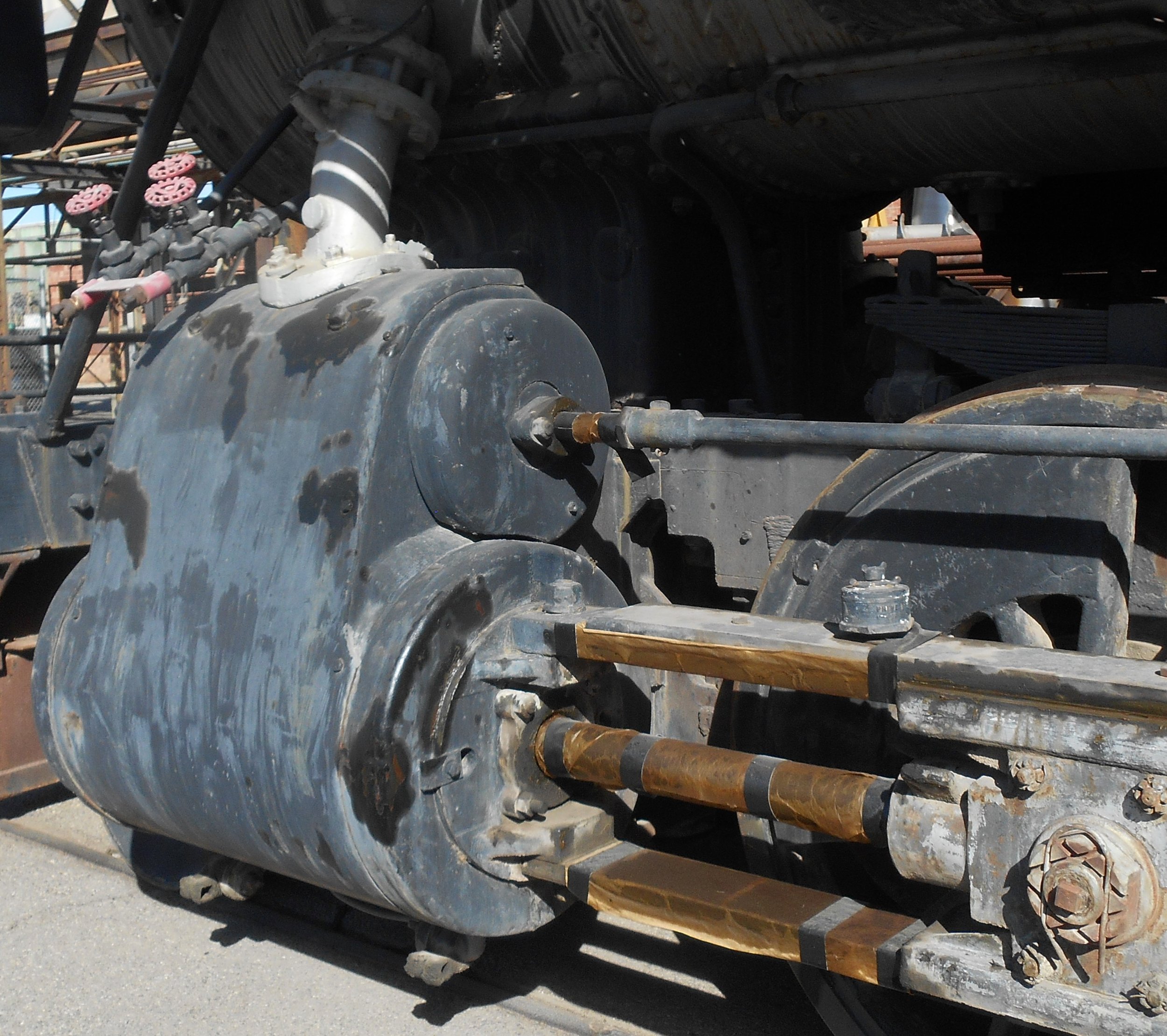
1. Air Compressor Governor
2. Air Compressor
3. Air Reservoir
4. Bell
5. Boiler
6. Boiler Blow Down
7. Brake shoes
8. Cab
9. Crosshead
10. Cylinder
11. Driving Wheel
12. Dynamo
13. Firebox
14. Front Coupler
15. Headlight
16. Injector
17. Oil Tank
18. Pilot
19. Pilot wheel
20. Rod main
21. Ride side
22. Running board
23. Sand Dome
24. Smoke Stack
25. Steam Dome
26. Train Number Indicator
27. Turret
28. Valve Steam Chest
29. Water Tank
30. Whistle
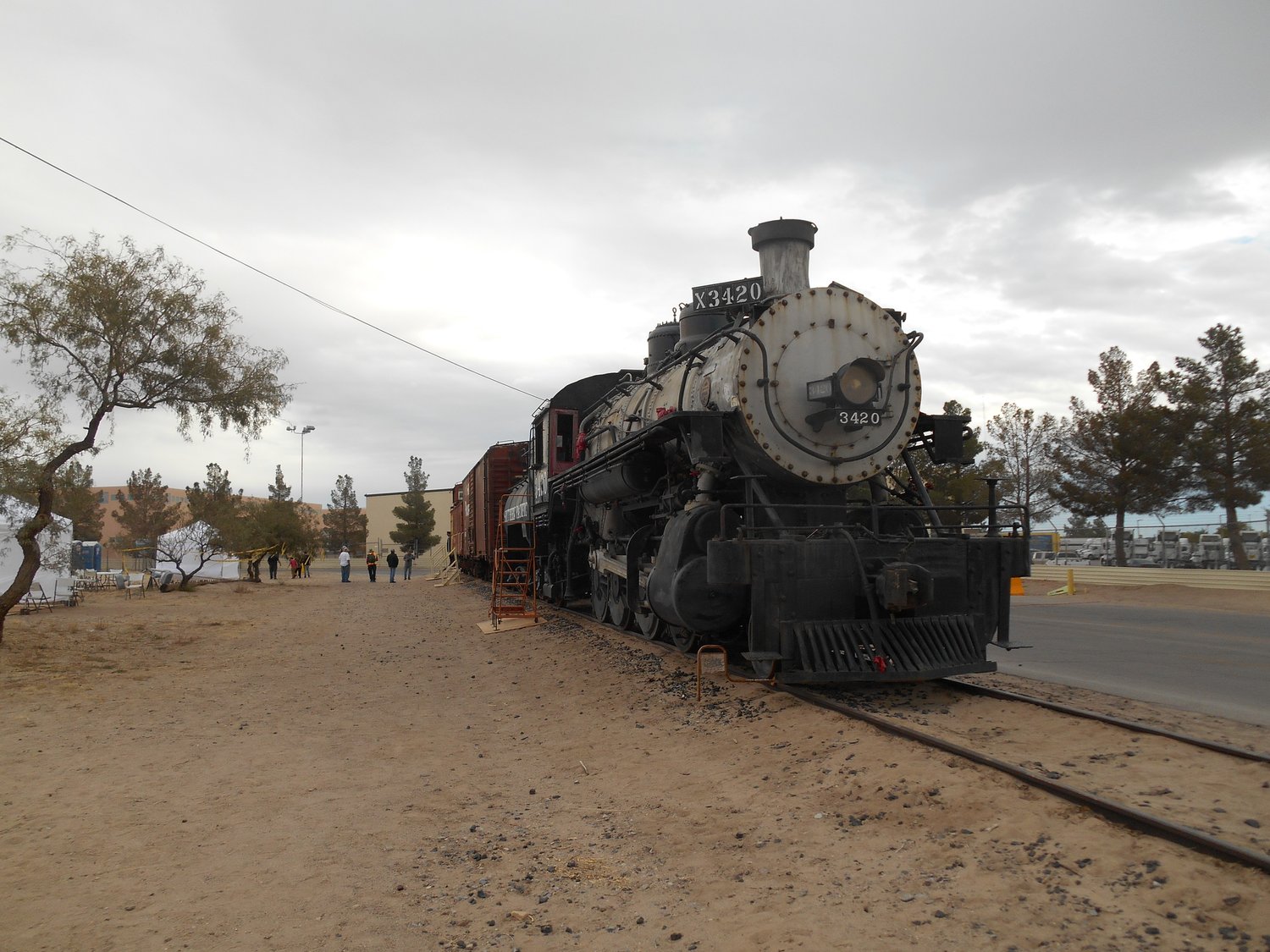
The above and below photos were taken after the El Paso Train Show on November 4 2017 by Robby Peartree
Engineer’s Side Location of My Appliances

1. Air Reservoir
2. Bell
3. Boiler
4. Boiler Blow Down
5. Brake Shoes
6. Cab
7. Crosshead
8. Cylinder
9. Driving Wheels
10. Dynamo
11. Firebox
12. Front Coupler
13. Headlight
14. Hydrostatic lubricator line
15. injector
16. Oil Tank
17. Power Reverse
18. Pilot
19. Pilot Wheel
20. Rod, Main
21. Rod, Side
22. Running Board
23. Sand Dome
24. Smoke Stack
25. Steam Dome
26. Train Number Indicator
27. Turret
28. Valve
29. Water tank
30. Whistle
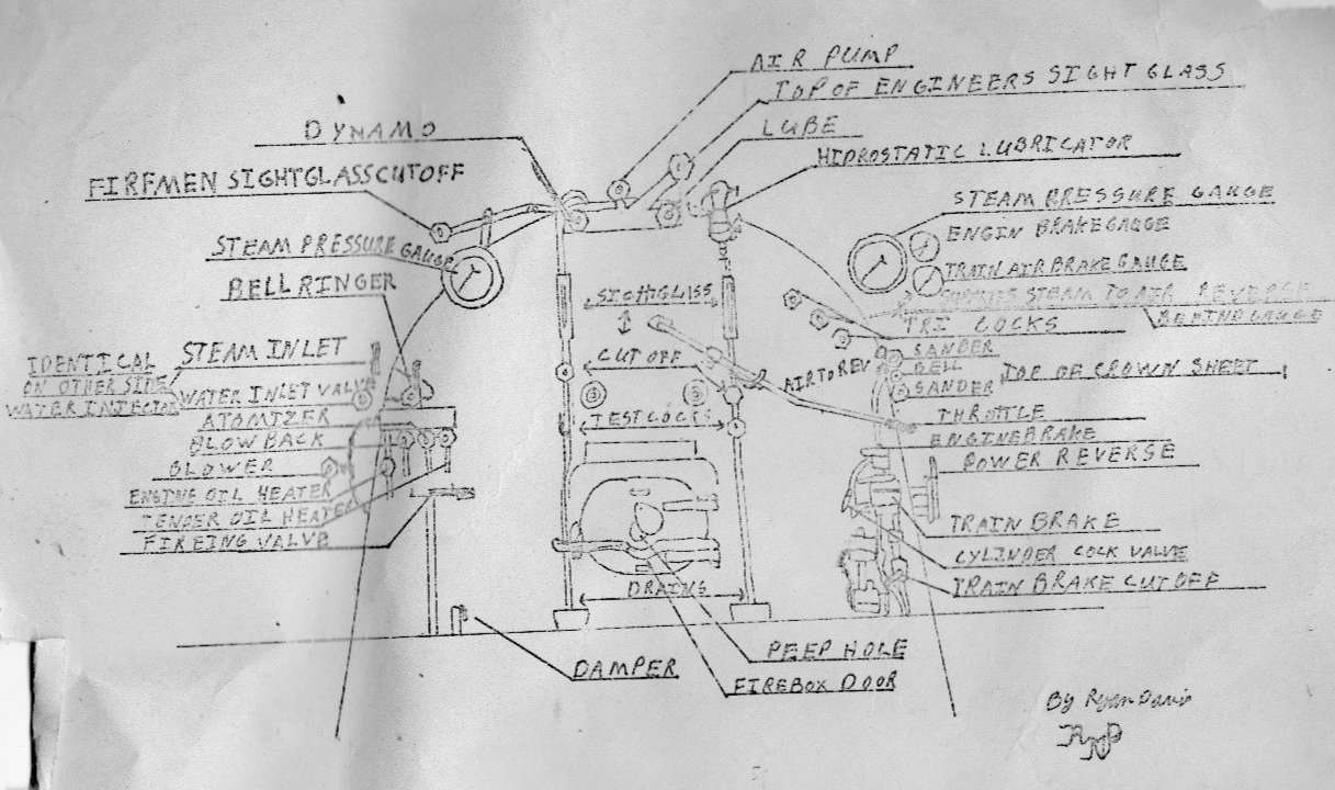
This drawing was provided to the Southwest Chapter of the Railway & Locomotive Historical Society by then member Ryan Davis to help fellow members learn the layout of the unlabeled valves in Southern Pacific 3420’s cab.
When an engineer receives the signal to move from a brakeman or conductor they acknowledge the signal, move my power reverse to the appropriate direction, release the independent brake valve, slowly begin to open my throttle valve in my steam dome which sends team through my dry pipe, superheaters, past my valves and to my cylinders until steam appears at my cylinder cocks while carefully watching for a sudden or unexpected change in sound or signal. As the pressure slowly builds in my cylinders, the steam will push on the pistons in my cylinders to allow me to start me to start moving. As the metal is heated by the steam, the steam will no longer easily condense back to water and the engineer can close my cylinder cocks. After the cylinder cocks are closed and the issues of condensate in my cylinders are adverted and I am hot and ready for service the engineer can use any of the over 60 notches on my throttle.

The above photo shows the number of teeth to position the power reverse ro reposition the locomotive valve timing. The lower valve in the photo is the rear sander.

The above photo shows the length of the throttle lever. We see where the throttle latches to the bar to maintain the desired throttle opening.

This photo shows the number of teeth that the engineer has avaliable to position the throttle.
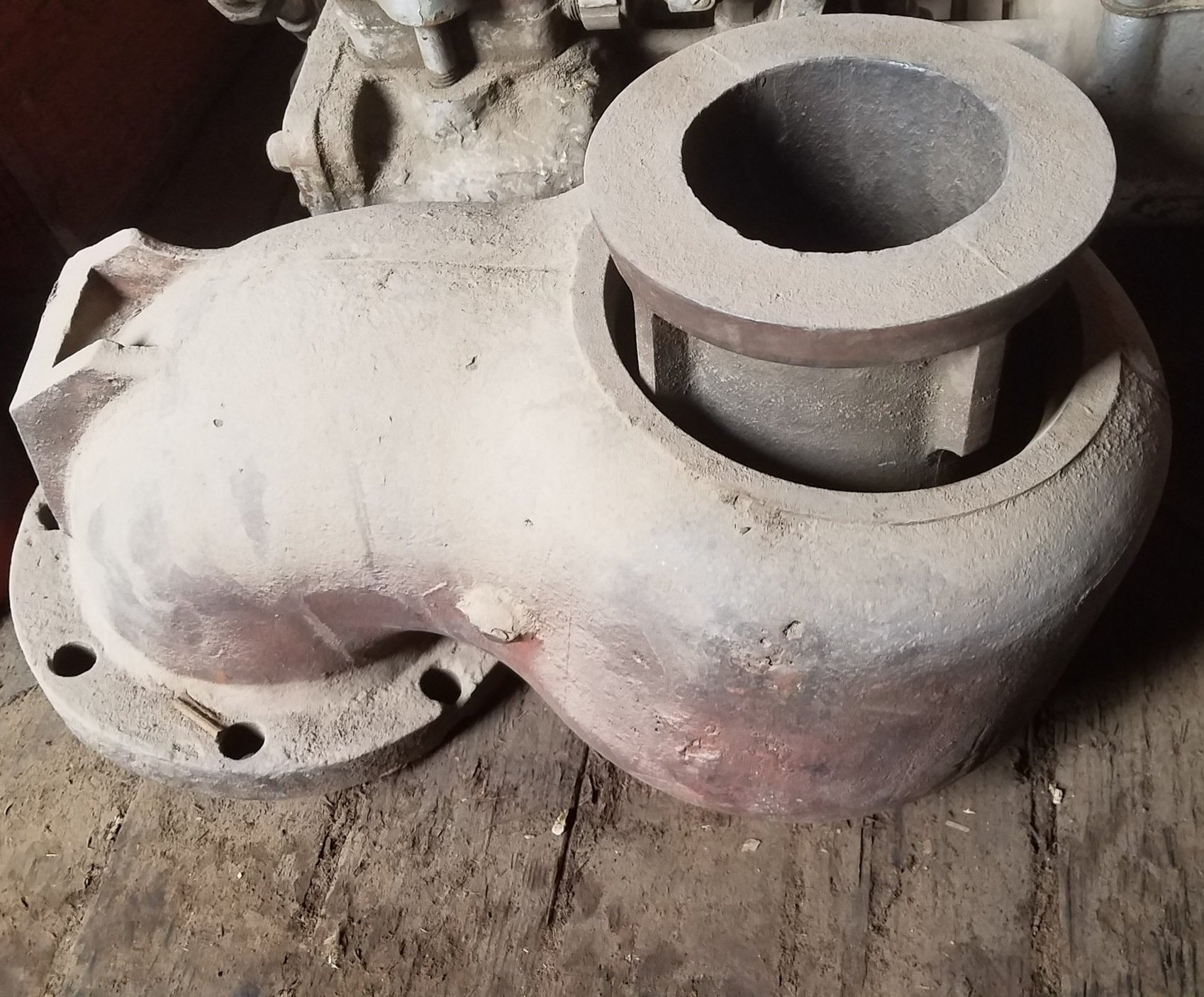
The photo above shows the throttle valve as it sits out of my steam dome and in the storage in Southern Pacific Box Car 115497. The throttle valve is taken out of the steam dome as access to the interior of the boiler is often accomplished by descending down from the steam dome onto the top of the tubes to inspect the interior of a locomotives boiler. Photo by Robby Peartree.

The photo above is part of the interior of my smoke box showing my petticoat and superheater/ superheader header assembly. Photo by Robby Peartree. 12-28-21
S Superheater
H Header
P Petticoat
D Dry pipe
F Flue
T Tube

This is some of the printed material by the Elesco Company covering various subjects on the superheater. This Gives a good demonstration of how steam flows from the boiler past the trottle, through the superheater header, into the superheater, back into the superheater header and then to the valve in the cylinder casting.
Another view of the piston. Thus provides a view of the piston packing tp prevent steam loss. Steam enters the pistons after leaving the superheaters steam enters the valve and the cylinders to pish the pistons to rotate the locomotive’s drivers.