My Descriptive RecorD

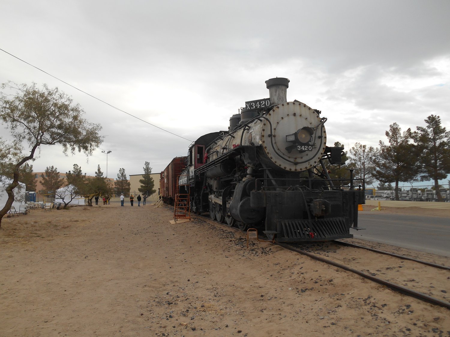
The fireman’s Side of Southern Pacific 3420 just before the November 2017 El Paso Train Show. The location is the tail of the switching spur in the FreePort McMoRan Copper Refinery near the Jack Bell Ball Park. 3420 operated for the dedication of the ball park in 1985
My Construction
Date Built: August 1904
Builder: Baldwin Locomotive Works
Where Constructed: Philadelphia, Pennsylvania
Builder’s Number: 24586
My Ownership History
Original Owner: El Paso & Northeastern Ry
Second Owner: El Paso & Southwestern RR
Third Owner: Southern Pacific RR
Current Owner: City of El Paso, Texas
Sunsetted City of El Paso Boards that have had oversight of Southern Pacific 3420
El Paso Historical Railroad Board, City of El Paso Ordinance 7120 on February 10, 1981 and amended by Ordinance 7834.
El Paso Transportation & Industrial Archaeology Board City of El Paso Ordinance 10583 on May 7, 1991.
To see the legal papers go to 3420 legal papers.

Above is the last locomotive diagram that the Southern Pacific produced for 3420 from March 1, 1950.
Railroads would often create a booklet of drawings with information on each class of locomotives that they own. This way employees in the field could quickly refer to the drawings for certain information. The longer a class of locomotives served on a railroad, the class members would often develop differences within the class. For instance, at the end of 3420’s service on the Southern Pacific, 3420 had its own page in the locomotive diagram book, page C-19a. (research continues as to why)
The information given varies from between railroads. The El Paso & Southwestern typically showed the assigned tender for the class in the locomotive diagrams. The Southern Pacific typically did not assign a single design of tenders to a class of locomotives and therefore the Southern Pacific issued a separate Tender Diagram book. One reason for the assigning several different designs of tenders to one class of locomotives on the Southern Pacific was the Southern Pacific would often assign locomotives of the same class to different assignments. The C-18 and C-19s Southern Pacific were assigned to both switching and branchline duties. A number of different classes of tenders were used behind the locomotives depanding upon the locomotive’s usual assignment.
When studying a photograph, the the type of pilot installed, tender characteristics including oil and water capacities, the reaward visibility from the cab over the tender, and if the locomotive is equipped with train number indicators willprovide the viewer a glimpse into the regularly assigned duties for the locomotive. Southern Pacific 3420 was regularly photographed without train number indicators which indicates that 3420 was primarily used for yard switching on the Southern Pacific.
My Basic Information
WHEEL ARRANGEMENT: 2-8-0 (using the Whyte Classification System)
MY DIMENSIONS
RIGID WHEEL BASE: 16 Feet.
WHEEL BASE: 24 Feet 7 Inches
DISTANCE BETWEEN PULLING FACE AND CHAFING IRON: 38 Feet 11 7/16 Inches
CAB HEIGHT: 13 Feet 10 1/4 Inches
STACK HEIGHT: 15 Feet 2 1/4 Inches
WEIGHT ON DRIVERS: 177,800 Lbs.
TOTAL LOCOMOTIVE WEIGHT: 198,500 Lbs.
Weights are after the installation of the superheaters in 1918 which added approximately five tons to the total locomotive weight.
TENDER LENGTH BETWEEN PULLING FACE AND CHAFING IRON: 28 Feet 3 1/2 Inches
TENDER HEIGHT: 12 Feet 11 3/8 Inches
(The heights of railroad equipment are taken from the top of the rail for a consistent reference point.)
FUEL: Oil
CAPACITY: 2,200 Gallons.
TENDER: 126,000 Lbs.
LOCOMOTIVE AND TENDER WEIGHT FULLY LOADED: 324,500 Lbs. or 162.25 Tons
(Source UTEP Library Special Collections Department Southern Pacific Collection MS 077 Locomotive and Tender Diagrams)
CYLINDER DIAMETER: 22 ½ INCHES
PISTON THRUST 79,520 LBS (Source Locomotive Data The Baldwin Locomotive Works Eleventh Edition 1939 Philadelphia PA, Pg 58.)
CYLINDER STROKE: 28 Inches
DRIVER DIAMETER: 57 Inches
BOILER PRESSURE: 200 Psi.
TRACTIVE FORCE: 42,280 Lbs.
BOILER TYPE: EXTENDED WAGON TOP
BOILER SAFETY VALVES: 3 INCH CROSBY
NUMBER OF SAFETY VALVES: 2

3420 is equipped with two safety valves at the top of the boiler. The spring loaded valves are designed to open repeadiately at the same pressure without having to be reset. The capacity of the safety valves on a boiler should exceed the steam producing capacity of the boiler to prevent the boilers failure.
INJECTORS: Two
Type: NATHAN SYMPLEX LIFTING 11

I am required by federal law to have two ways of putting water into my boiler. To meet this requirement, I currently have two lifting injectors, one is on each side of the boiler. A lifting injector lives on the side of the boiler and the water is lifted by steam to the injector.
To operate the injector the water valve is turned on and then the sliding steam handle is partially pulled back until water appears at the overflow showing the overflow showing that the injector is primed. It is then fully pulled back to increase the steam flow and start placing the water into the boiler. You then adjust the water valve to control the rate of water input into the boiler. To shut the injector of you first push the pull handle to stop the steam. You then close the water valve leaving it at ¼ turn from the fully closed position. The water flowing thru the valve has cooled I the valve causing it to contract and without the water flowing thru it the metal expands. If the valve is tight the result is it swells to a very tight condition that takes a wrench to reopen it.
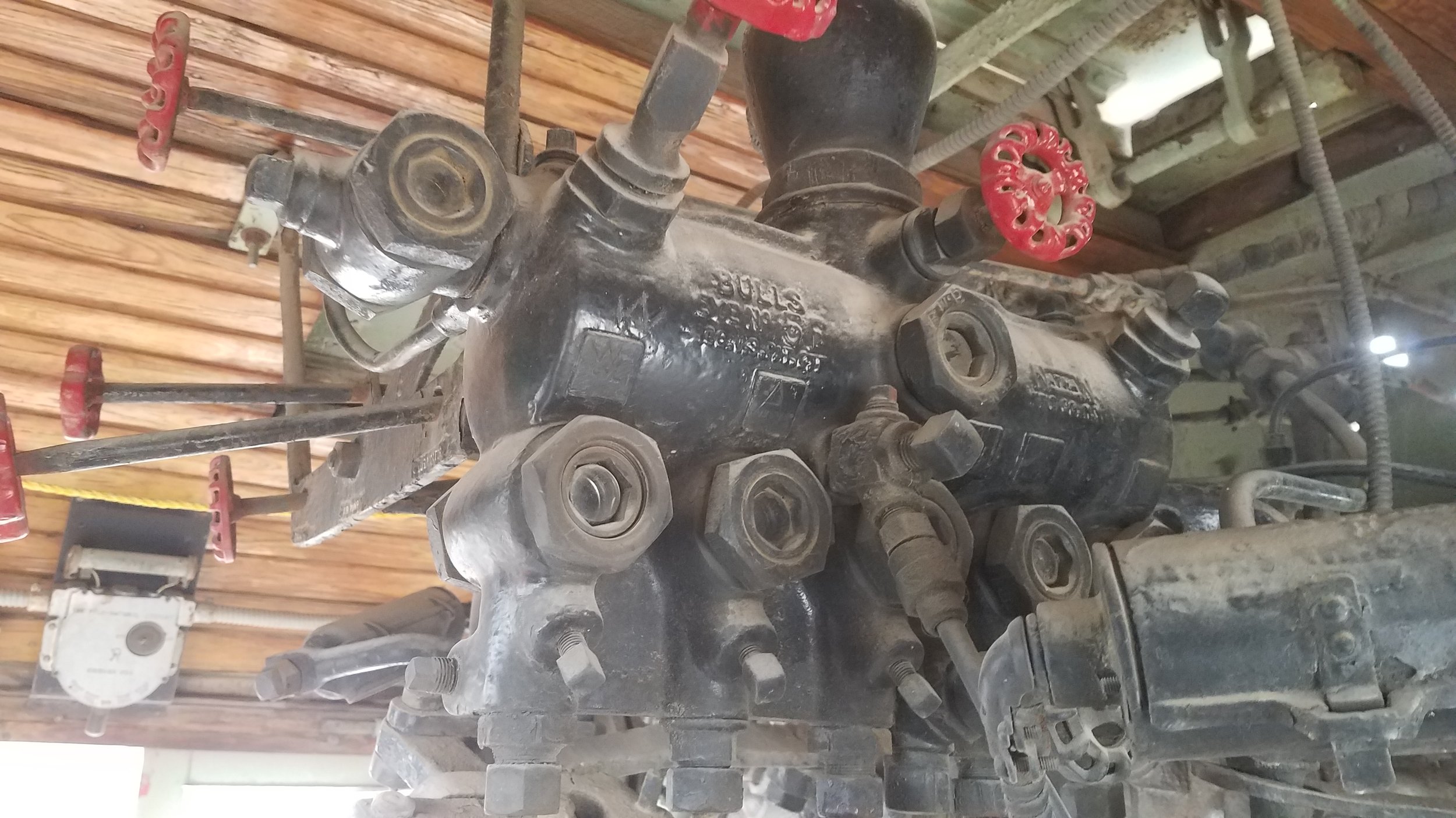
BOILER CHECK VALVES: NATHAN REVERSIBLE

This photo shows my fireman’s side check valve. This photo also shows the boiler patch applied by the SP on December 31, 1944. Photo by Robby Peartree
This I am equipped with two boiler check valves. A check valve is a valve that permits the flow in only direction. My Boiler Check Valves are located where the flow from the boiler injectors enters my boiler. This prevents the boiler pressure from flowing to the injector. The operation of the check valve is automatic by the use of boiler pressure and the flow from my injectors.
This I am equipped with two boiler check valves. A check valve is a valve that permits the flow in only direction. My Boiler Check Valves are located where the flow from the boiler injectors enters my boiler. This prevents the boiler pressure from flowing to the injector. The operation of the check valve is automatic by the use of boiler pressure and the flow from my injectors. I am currently equipped with reversable check valves manufactured by the Nathan Manufacturing Co.
WATER GLASSES: KLINGER 8 5/8-INCH REFLEX GLASS

A fact about liquids is that any liquid will constantly seek its own level. The water glass operates based on this basic principle. The water glass communicates with a boiler at two locations. One location is at or near the top of the boiler. The second location is typically lower than the firebox crown sheet. When a fire tube boiler is operating normally, This allows the steam from the boiler to enter the glass at the top and water to enter at the lower connection. The bottom of a water glass is to be set at a height of at least three inches above the highest point on the crown sheet (See 49 CFR part 230.51 Number and Location under Water Glasses and Gauge Cocks).
Each water glass can be isolated from the boiler by closing the two shut off valves. In addition each water glass is required to be equipped with a drain valve to drain the water glass (See 49 CFR 230.52 Water Glass Valves). To see the information on the brass plate on the water glass see the next photo.
Checking for proper Operation of the water glass
To check a water glass for proper operation first observe where the water level is in the glass before starting the test.
Crack open the drain valve. This should be open a small amount to avoid diging up ballast and throwing it at people. Notice the water drain from the water glass and the associated noise. The noise is a rumble type sound.
Then close either the top or bottom valve. The glass should then show the fluid for the valve that remains open.
Then close the other valve and the water glass should both drain completely and the glass should be isolated from the boiler. Incase the glass breaks or a repair needs to be made you need to be able to isolate the water glass. By performing this test daily you are monitoring the ability of the valves to isolate the water glass.
Then fully open the first valve you closed. You should see the water glass fill with either steam or water depending on which valve you open first.
Now open the other shut off valve.
Close the drain valve.
Finally observe that the water returned to the same level. If the water level did not return to the same level, something is wrong.
This proceedure is a basic daily inspection of a water glass. It will not tell you if the boiler is foaming or experiencing other issues.

The hand stamped metal tag in the photo states;
“Insure Safety On Max Grades Water Must Fall Below This Level.”
When a water glass is operating properly, the water in a water glass is inflenced by the vibration of the operation of the locomotive. When a steam locomotive is in motion the water level can change up to an inch or more over track where the grade and curvature are consistant. Because of this bobbing of the water level, the water level that one would estimate is an average of the bobbing interface between the water and steam.
Water Glass Brass Tags used on the southern pacific
Prior to the current Federal Code of Regulations requiring two water glasses, stem locomotives were only required to be equpped with one wter glass in the United States. The Southern Pacific equipped their locomotives including 3420 with two water glasses.
Steam locomotives were assigned to a division or portion of the railroad. Each division would have a timetable indicating any operating restrictions for each class of locomotives. The territory would also have certain caracteristics including ruling grades. To assist crews with maintaining the minimum level of water to safely operate over the railroad the Southern Pacific installed the brass tag seen in the adjacent photo. 3420 was assigned to operate on the Rio Grande Division. The Rio Grande Division was known for relatively flat territory resulting in the closest placement of the tags to the top of the crown sheet on the Southern Pacific.
Steam Locomotives and Vertical Curves
The importance of water level on a steam locomotive is the simple issue of preventing a catistrofic boiler failure. Water at 200 psi boils at 393 F. A firebox can reach a maximum temperature near 3000 F. The diiferences in temeerature between the fire in the firebox, the water in the boiler, and the ambient air temperature create a temerature gradiant from the fire to the outside of the boler. The highest melting point of steel is 2800 F and the addition of carbon will cause the melting point to drop slightly. Iron also undergoes changes to the atomic structure at certain temperatures below 2800 F. The ability of the steel to take stress and strain loading is dependent upon temperature.
Understanding the basics of the material characteristics of a steam locomotive, it is important to keep the steel of the firebox sheets relatively cool to keep the steel strength in the needed range for safe operation. Properly operating water glasses are critical to having the proper water level to suffiently cover the firebox side sheets and have several inches of water over the crownsheet. unfortunately railroads do not always operate on level track.
Any liquid will flow to a position where the top surface of the liquid is level. On a steam locomotive where the firebox trails the smoke box, like 3420, if the locomotive is headed forward up the hill, the water will build up over the firebox. If the locmotive crest the top of the hill and starts down the other side the water in the boiler will head to the front of the locomotive. This reduces the amount of water around the firebox. This is the reason for having a minimum level to maintain in a boiler when operating up the maximum grade of the railroad. This does not tske into account the effect of the application of the train brakes and the resulting sloshing of water to the front of the boiler usually lasting for a few seconds. It is difficult to account for water slosh which may cause the water to disapear from the glass. The water needed to cover a firebox once the braking force stablize is marked by the plate on the water glass. For some operating conditions and rate of brake aplicationsit is impossible to constantly have water in the glass. In these cases the water should return within a few seconds of the water disapearing from the water glass.
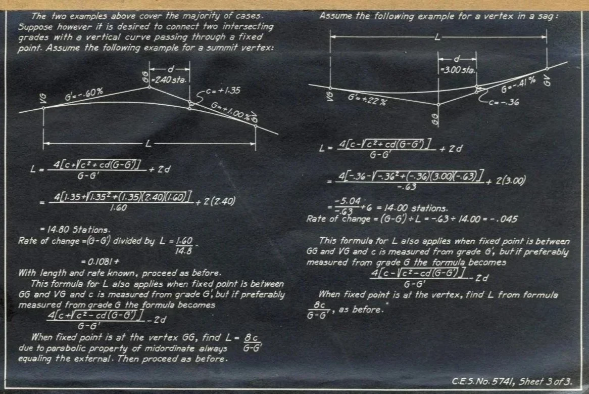
The page on the left is a part of a packet to assist the field survey crews in transitioning from one grade rate to another. We have a visual representation of a vertical curve. Vertical curves are encountered when a light locomotive or train cencounters a grade change. At far left the curve represents the situation when a cresting over the summit of a hill. The curve on the right of sheet shows the type of vertical curve encountered when a locomotive or train tranverses a dip or at the base of a grade.
SUPERHEATERS: SCHMIT TYPE A

This photo shows the superheater units leaning the 5-3/8 inch flues and bending to the super heater header you also see the several of the 210 2-inch tubes in the boiler. Photo by Robby Peartree

3420 was not origionally built with superheater units. Superheater units were installed in October 1918. The installation of superheater units created several benefits to reducing the operating costs of a locomotive. This was accomplished by increasing the thermoal effiency of the locomotive. The boiling point of water in a steam locomotive boiler operating at 200 psiis 393 F. If the locomotive is operating with a wide open throttle, the temperature of the steam can reach a maximum temperature of 675 F when leaving the superheater. The temperature of the fire in the firebox are known to reach 2800 to 3000 F depending on the fuel. Exhaust temps at the stack are still above 1000 F.
Superheater introduces the saturated steam from the boiler to the waste heat of the exhaust gas to accomplish this temperature increase. New boiler front and rear tube sheets were installed to accept the 30 5-1/2 inch flues that the superheater units would slide into. The location of the front tube sheet was moved 4-inches toward the back of the boiler to accomidate the installation of the locomotive superheater header. additionally the slide valves for the pistons were removed and a conversion attachment for a piston valve was installed. The cylinder casting you see today were installed at a later date.
A superheated steam locomotive uses 10% less water than the same locomotive without superheaters.
THROTTLE VALVE:
RUSHTON DOUBLE SEAT BALANCED VALVE
This valve is located in the steam dome. The reason the valve is located in the steam dome is the steam dome is the highest point in the boiler and the steam that reaches this height contains the least amount of condensing water vapor. On a steam locomotive without superheaters the amount of condensing water vapor is steam that is not only not doing work it also creates an opportunity for the pistons to build up with water.
The operation of the valve is designed to lift a larger area than the area that is pulled up into the valve chamber. The simular size of the two areas creates a relative balance of forces of the steam acting on the valve. The slightly larger top helps create the closing force on the valve. The closing force creates the resistance to opening the engineer feels when opening the throttle.
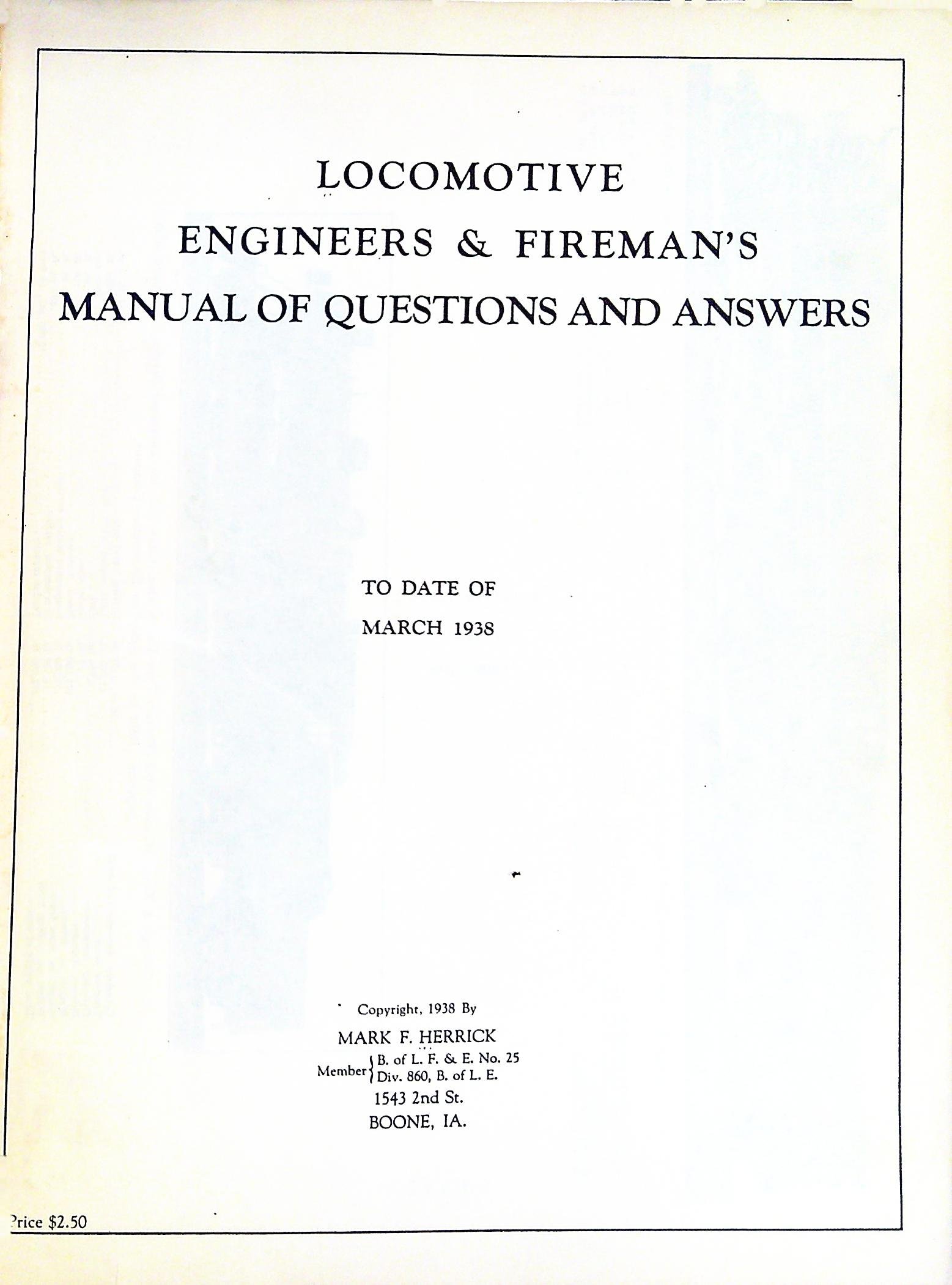
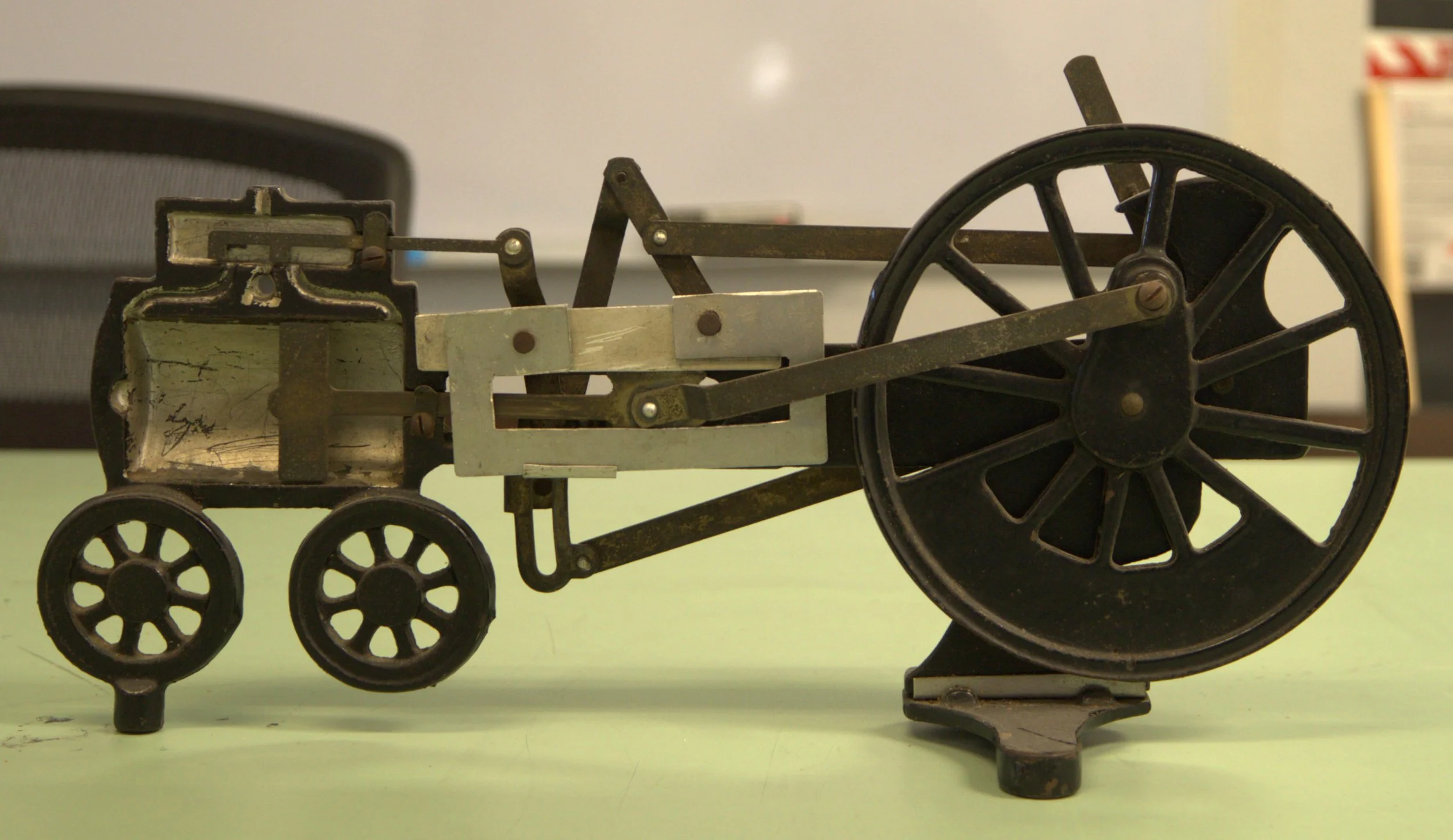
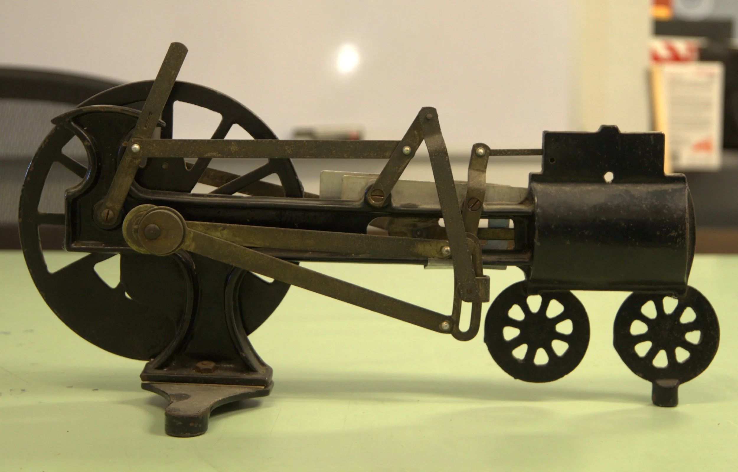
VALVE GEAR: STEPHENSON
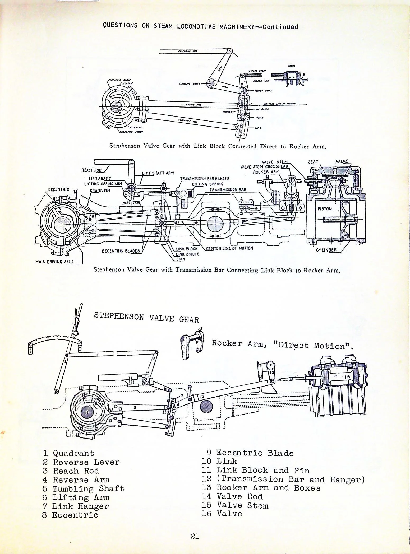
This set of drawings of Stevenson Valve gear appears in the book Locomotive Engineers & Fireman’s Manual of Questions and Answers by Mark F Herrick
Hydrostatic Lubricator: Nathan Five Feed
Mechanical Lubricator: None
PISTON RING SLOT: BOX TYPE
PISTON RING NUMBER: 6
PISTON RING SIZE: 9/16” BY ¾”
Piston Rod Packing: P&M
POWER REVERSE: RAGONET 9-INCH

ENGINE TRUCK or PILOT TYPE: SWING CENTER

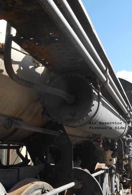
AIR BRAKES: WESTINGHOUSE ENGINE and TENDER #6

AIR COMPRESSOR GOVERNOR TYPE: SD

AIR COMPRESSOR: WESTINGHOUSE 8 1/2 INCH CROSS COMPOUND

AIR RESERVOIR VOLUME: 67,179 CUBIC INCHES
INDEPENDENT BRAKE VALVE: WESTINGHOUSE S-6

AUTOMATIC BRAKE VALVE: WESTINGHOUSE H-6

BELL RINGER: VILOCO (Missing)
CYLINDER COCKS: AIR

Sanders: Air Operated
Type: Leach


The lower valve handle operates the rear sanders and the solid valve handle operates the pneumatic ringing of the bell. The valve at the top with the handle outside of the photograph operates the front sanders. On 3420 sand is applied ahead of the second driver and behind the third driver. The firebox limits the placement of the rear sander any further back and the front sander is placed behind the first driver to avoid sand in the cross heads.
DRAW GEAR: 1 DRAW BAR 2 SAFETY CHAINS

GENERATOR: K2 TURBO GENERATOR

HEADLIGHT: 18-INCH ROUND CASE PYLE NATIONAL


(California State Railroad Museum Southern Pacific Form C.S.-4395)